NEXT LEVEL
SEISMIC DESIGN
IRANDAMP VISCOUS DAMPER PRODUCTS
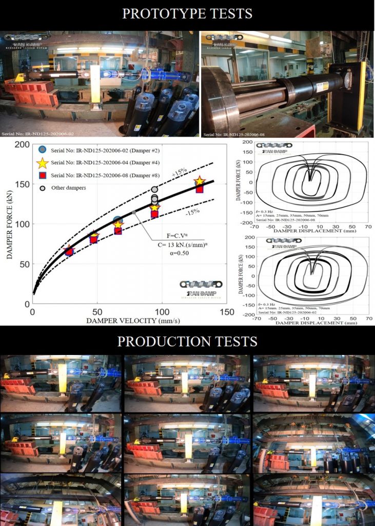
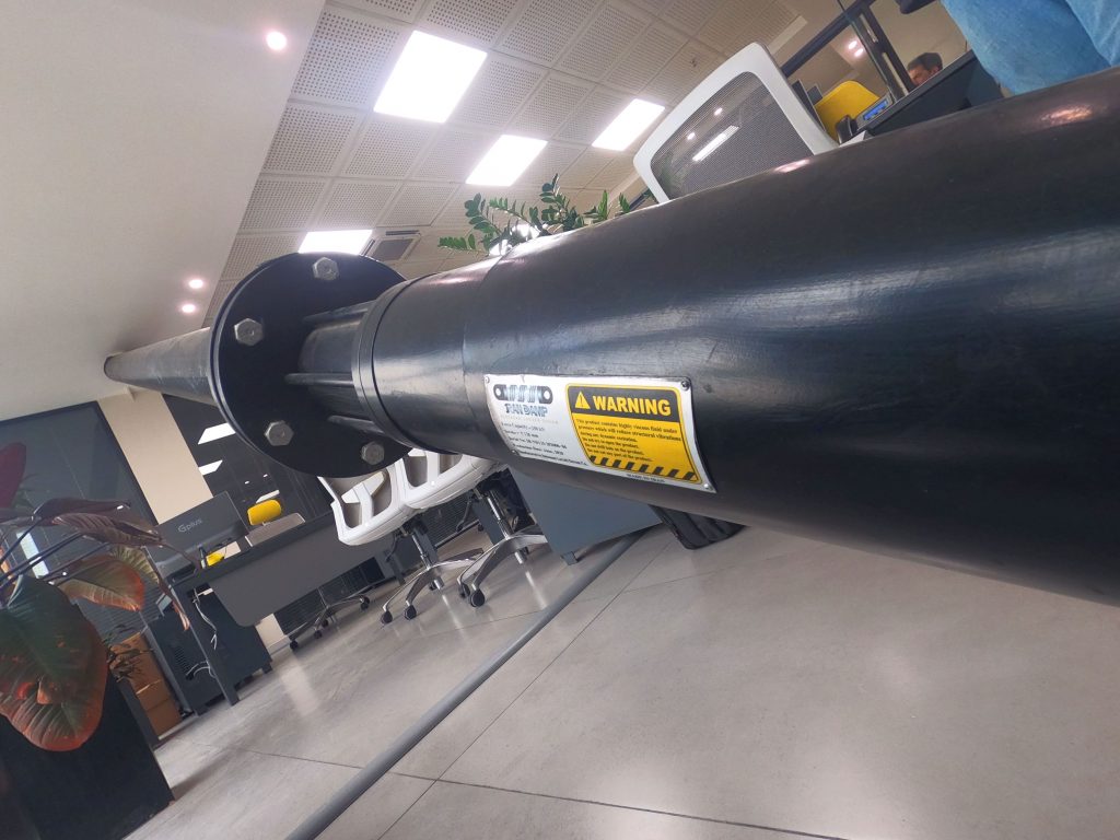
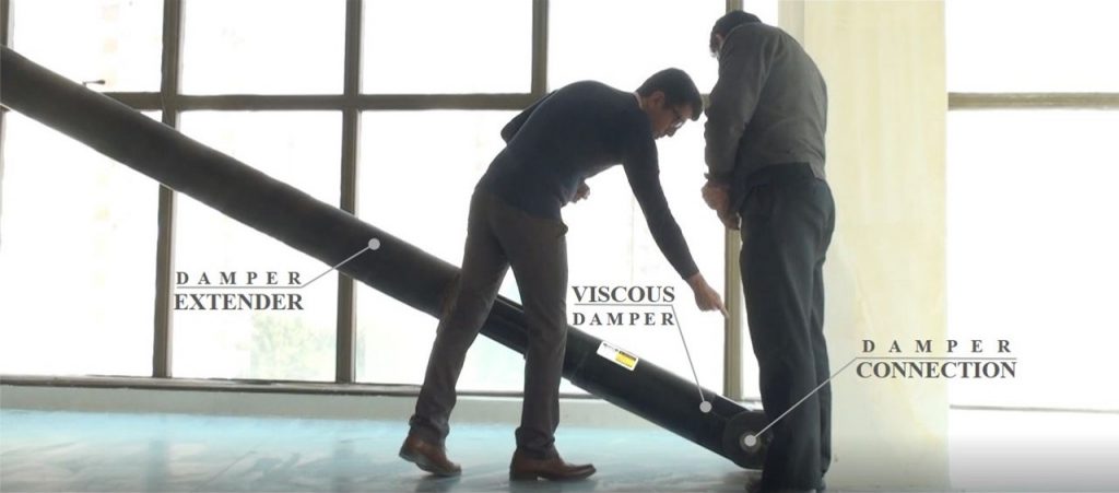
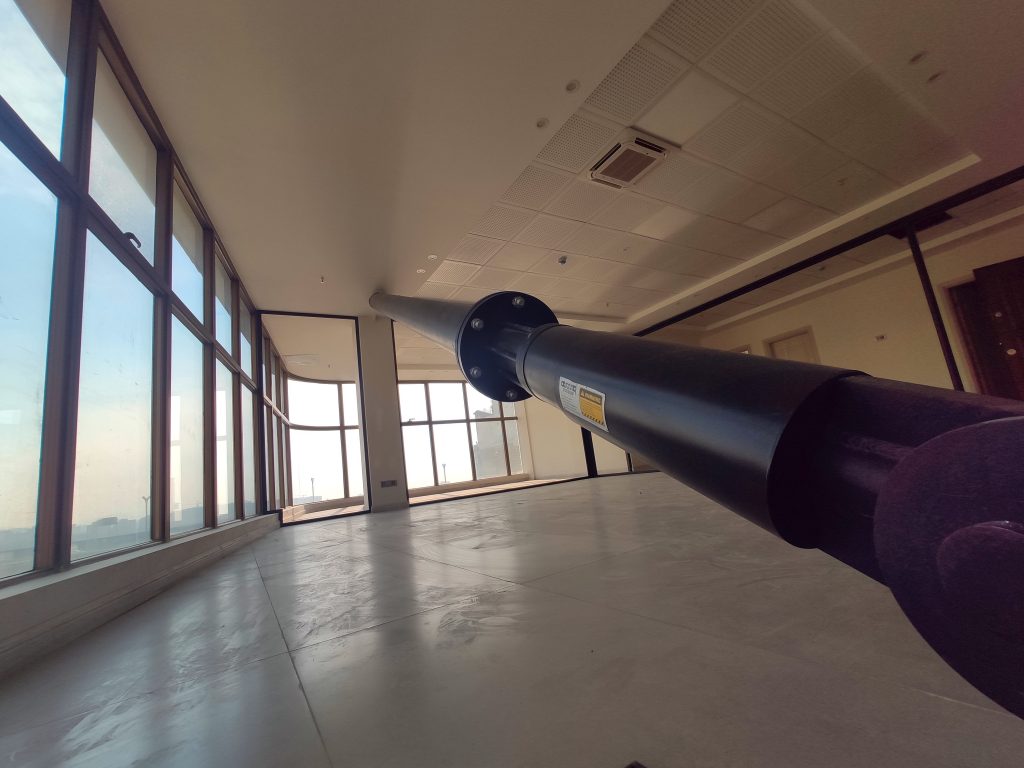
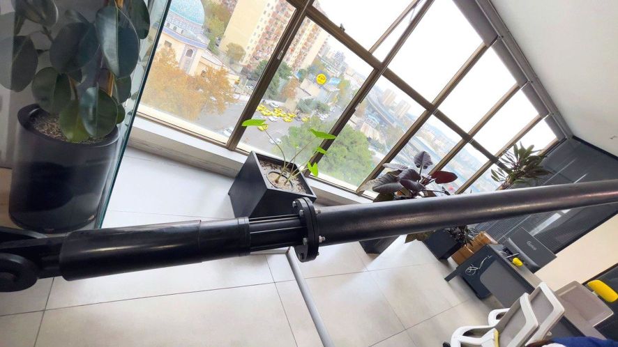
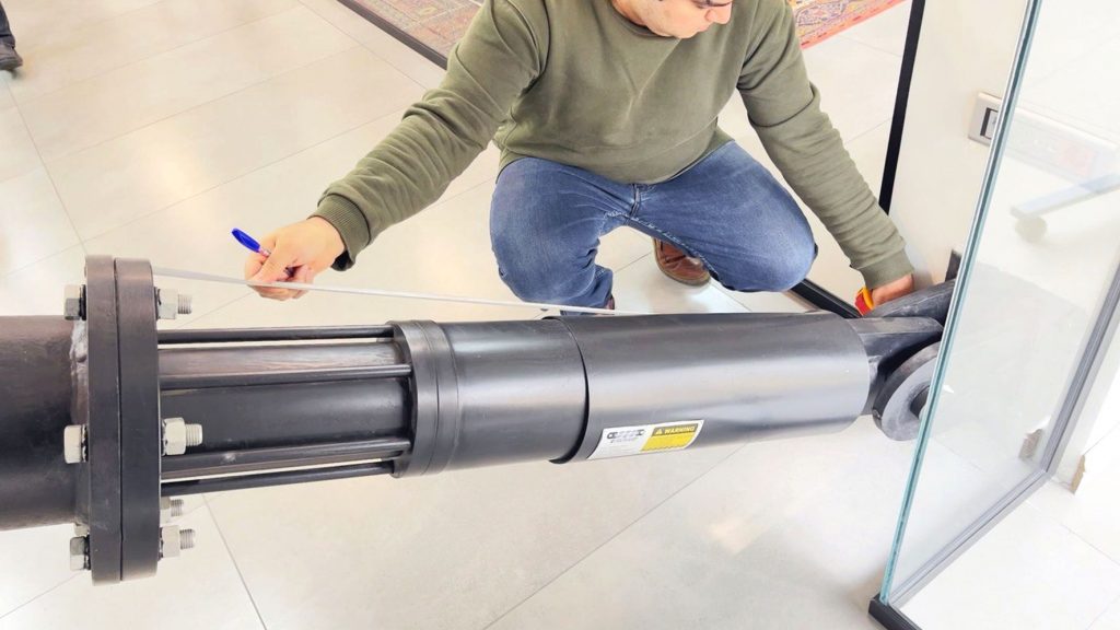
Characteristics of four viscous damper models manufactured by IRANDAMP is listed below. To review further details about each product, and test results, visit PRODUCTS and GALLERY pages. Moreover, TECHNICAL POSTS contains comprehensive technical points about viscous dampers and other vibration control devices.
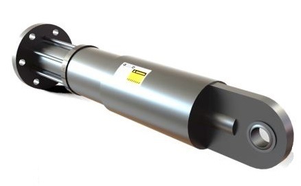
Model: Customized
Capacity: up to ±500 kN
Stroke: up to ±150mm
Damping coefficient: Unlimitted
Velocity exponent: 0.3~1
Weight: –
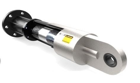
Model: IRD160
Capacity: ±500 kN
Stroke: ±120mm
Damping coefficient: Unlimitted
Velocity exponent: 0.3~1
Weight: 200 kg
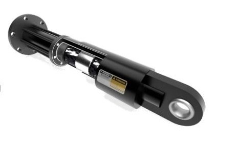
Model: IRD125
Capacity: ±250kN
Stroke: ±120mm
Damping coefficient: Unlimitted
Velocity exponent: 0.3~1
Weight: 110kg
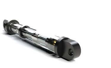
Model: IRD80
Capacity: ±100 kN
Stroke: ±60mm
Damping coefficient: Unlimitted
Velocity exponent: 0.3~1
Weight: 40 kg
FLUID VISCOUS DAMPER PLACEMENT CONFIGURATIONS
Fluid viscous damper, also simply called viscous damper, can be implemented in buildings using different configurations. Here are some common configurations for these velocity-dependent energy dissipating devices. Note that some of the available configurations have amplification properties which means the imposed damper displacement can be amplified. This would also amplify energy dissipation of the damper and reduce total number of the required dampers. A fluid viscous damper has zero static stiffness and can be placed along the height of the building in a discontinuous manner. As a result, fluid viscous dampers are not required to be placed at all stories and also it is not necessary to continue viscous dampers down to the foundation. Optimal placement of the dampers can be obtained based on IRANDAMP’s exclusive algorithm which is programmed to achieve a target damping ratio determined by the designer. The final configuration and damper placement would be selected based on structural and architectural considerations
For further technical details, visit TECHNICAL POSTS
For videos about viscous dampers watch the uploaded videos from here and here.
CONNECTIONS TO RC JOINTS
Fluid viscous damper energy dissipating devices can be used in new construction and/or rehabilitation of existing RC and steel buildings. Here are some details of viscous damper connections to RC beam-column joints. Respect the fact that viscous dampers are velocity-dependent which means their force would be out-of-phase with internal forces of the main structural elements. Despite conventional braces, viscous dampers would not increase force demands on other structural elements, such as adjacent columns and beam-to-column connections
For further details, visit TECHNICAL POSTS
APPLICATION IN BRIDGES
Fluid viscous damper is a velocity-dependent device and add no constraint for thermal deformations of the deck. Using viscous dampers, bearing deformations, pier moments and shears, abutment and foundation demands, and deck acceleration would be simultaneously reduced in both transverse and longitudinal directions. It is safe to say that the most seismic-resilient system for highway bridges and overpasses is to use flexible seismic isolation bearings supplemented with pure viscous damping provided by viscous dampers. This super efficient technique has been used in many seismic prone countries. Due to the lightness of an average span bridge deck, a couple of medium sized viscous dampers can easily increase damping ratio of the bridge to about 40% at both transverse and longitudinal directions. Such a huge amount of damping cannot be achieved by the bearings themselves or other yielding/friction devices
For more technical details, visit TECHNICAL POSTS
APPLICATION IN SEISMIC ISOLATION
Viscous dampers can be used at the isolation level of seismically isolated buildings. Viscous dampers have zero stiffness and can inject pure viscous damping to the seismic isolation system. The result would be reduction in deformation demands on the isolation bearings without affecting lateral stiffness of the isolated layer. Thanks to the zero stiffness viscous dampers, isolation bearings with lower stiffness can be used without any increase in lateral deformation of the isolated layer
Further details are available in TECHNICAL POSTS
P R O J E C T S
NOBONYAD TOWER

