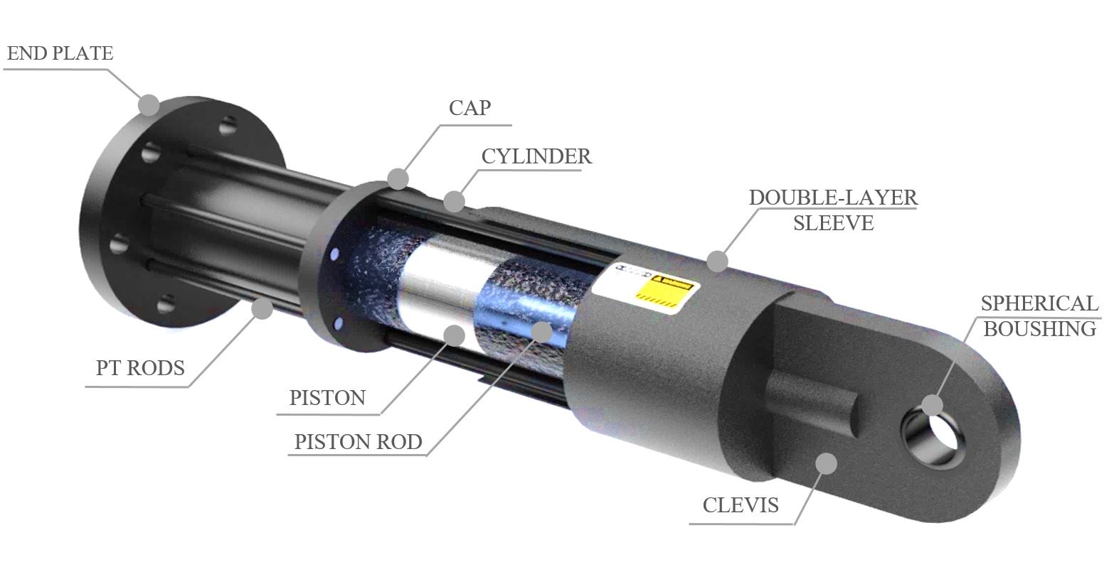
INSIDE THE VISCOUS DAMPER
Viscous Dampers are similar to giant shock absorbers which reduce structural vibrations during any kind of dynamic excitations such as earthquake, wind, wave, blast, impact and etc. The main components of a viscous damper are the main cylinder, piston, piston rod, orifices/valves and sealing system. During a dynamic excitation, the piston axially reciprocates inside the cylinder, which in turn pressurize the viscous fluid on one side of the piston, while the pressure of the other side is zero. Generated pressure difference, result in fluid flows through the orifice(s) of the piston which result in a hydraulic energy dissipation. Viscous damper would convert the input kinetic energy into heat energy which is called viscous heating. The heat would finally be transferred to the surroundings. IRANDAMP’s dampers are equipped with thermal compensation mechanism and built-in accumulator which lead to be stable cyclic behavior during a wide range of temperatures
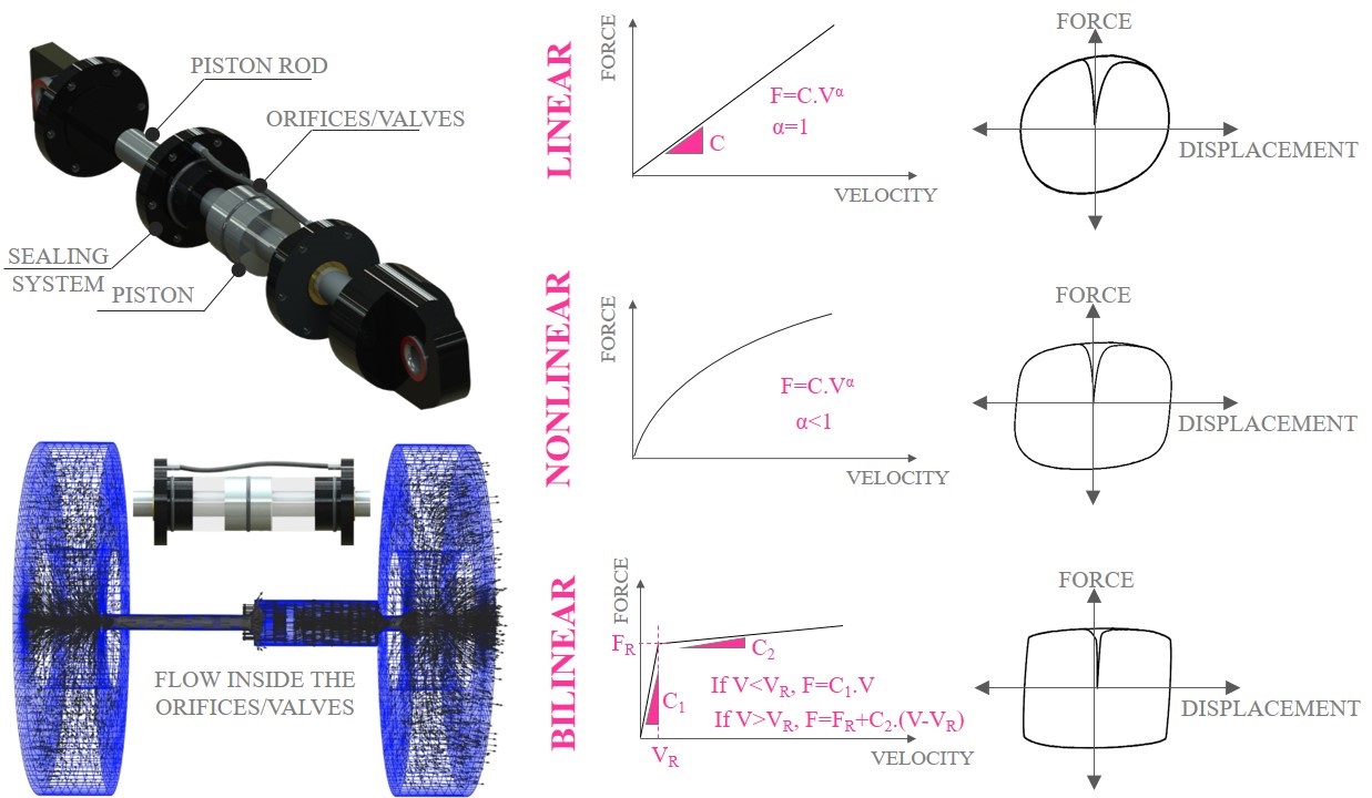
BEHAVIOR OF VISCOUS DAMPER
Viscous dampers are velocity-dependent energy dissipating devices. This means that damper force depends on the imposed relative velocity at both ends of the damper. Depending on internal details, different force-velocity behaviors can be achieved including linear behavior, nonlinear behavior and bilinear behavior. Damping coefficient (C) and velocity exponent (α) depend on the internal details of the damper which are confidential. Viscous dampers with linear force-velocity curve are called LINEAR VISCOUS DAMPER, and those with nonlinear force-velocity curves are called NONLINEAR VISCOUS DAMPERS. Dampers with bilinear force-velocity curves are called OIL DAMPERS. Although IRANDAMP are able to design and manufacture all three types of the aforementioned devices, nonlinear viscous dampers have received more attention by structural engineers.
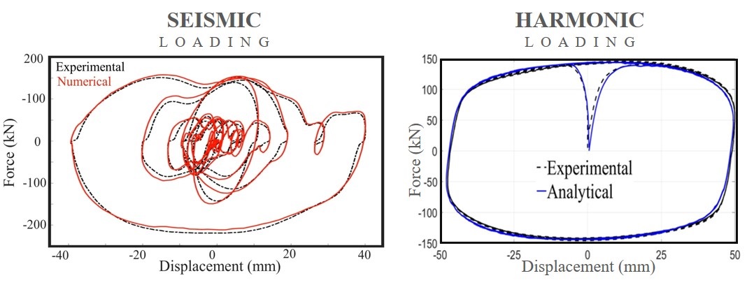
NUMERICAL MODELING
Dynamic behavior of viscous dampers can be simulated in most analytical Softwares, e.g. SAP 2000, ETABS, OpenSees, etc. Note that, IRANDAMP have carried out many cyclic and seismic tests on different viscous dampers and it can be verified that the available elements, such as Damper-Exponential Link element of ETABS, are able to accurately simulate realistic behavior of viscous dampers under different excitations.
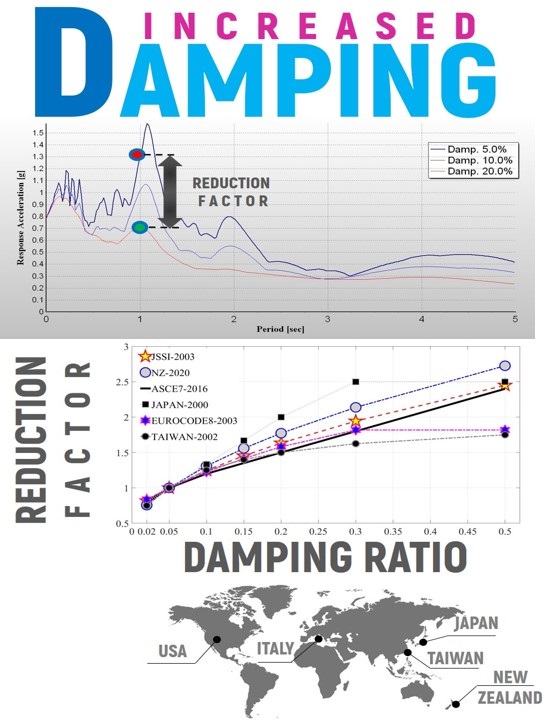
EFFECT OF DAMPING RATIO
It is well understood that damping ratio has significant effect on the dynamic behavior of structures. Inherent damping of a typical building is in the range of 2% to 5%. Fortunately, using supplemental energy dissipation devices, effective damping ratio can be increased. Among different energy dissipation devices, the highest achievable damping ratio belongs to viscous dampers which can be as high as 40% considering practical considerations. This is due to the fact that viscous dampers have zero static stiffness and inject pure viscosity into the structure. Different seismic codes and guidelines, such as ASCE 7, JSSI, etc., have introduced damping reduction factors with which the designer can approximate expected reductions in dynamic responses. For example, per ASCE 7, a damping ratio of 20% would roughly lead to 1.5 times, i.e. 33%, reduction in maximum responses. The response could be either base shear, story drift, story acceleration, etc.
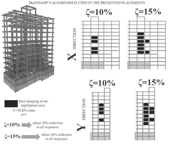
In order to reach to a predefined target damping ratio, IRANDAMP has developed an algorithm based on transfer matrix of the structure by which viscous dampers would be optimally placed at different stories to reach to the target damping ratio. Details of the procedure are published here.
It should be noted that the more the target damping ratio, the more the number of required viscous dampers. Achieving a very high damping ratio in the range of 30% to 40% is feasible for light and flexible structures such as low-rise moment resisting frames, seismically-isolated buildings and bridge decks on flexible bearings. However, in the case of heavy and rigid structures, target damping ratio is recommended to be less than 30%.
For further info about optimal placement of viscous dampers, contact us
OPTIMAL DAMPER PLACEMENT
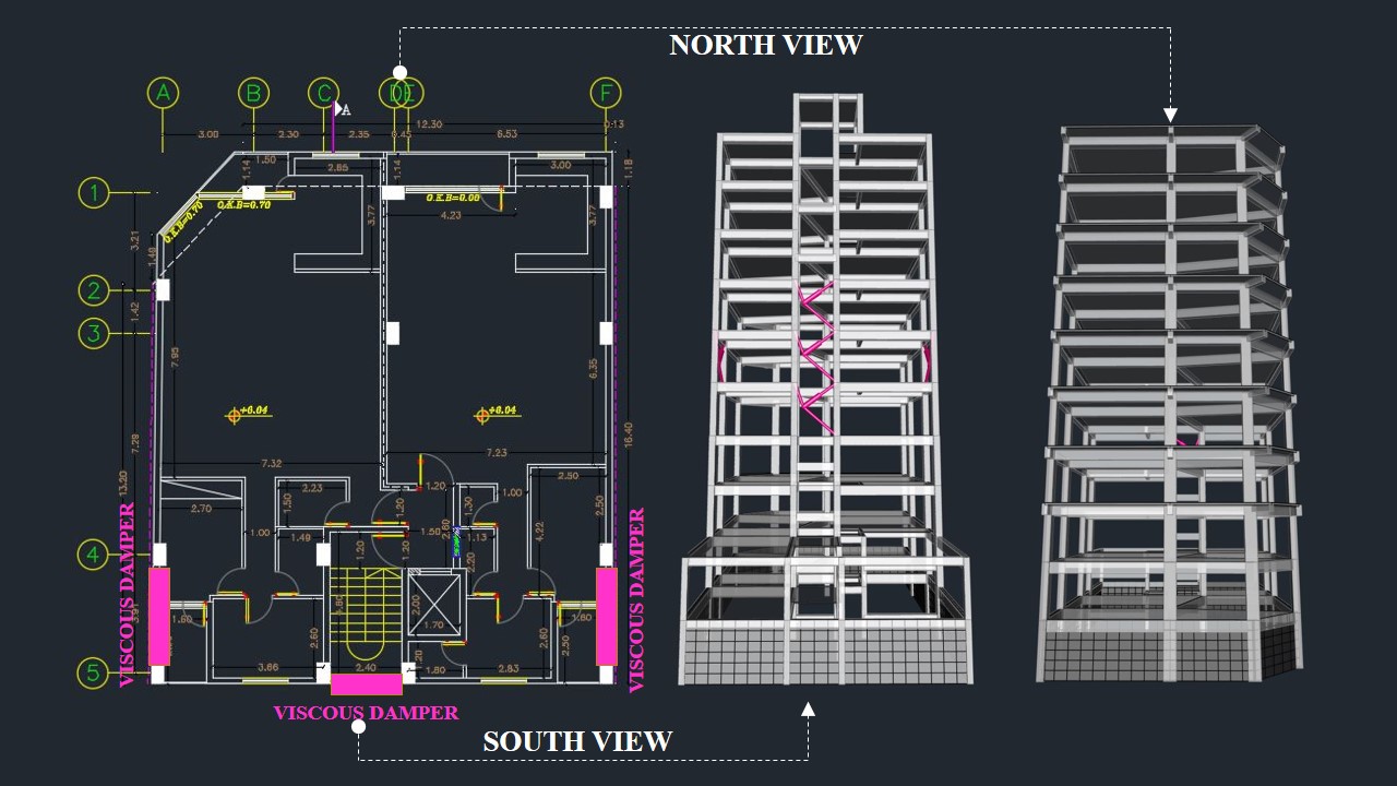
Considering a fixed number of viscous dampers with specified properties, the best seismic performance would be achieved if they were optimally distributed in the building. In other words, a uniform distribution of viscous dampers is not the best placement. Moreover, from construction cost point of view, it is desirable to reduce number of viscous dampers as much as possible. As a result, optimal placement of viscous dampers is a crucial task. Architectural limitations should also be respected during damper placement.
Therefore, IRANDAMP has developed an algorithm for optimal placement and characteristics of viscous dampers. To use the algorithm, you to need to send us seismic mass and lateral stiffness of your structure as well as inherent and target damping ratios. We would tell you which type of damper is suitable for your case and how many dampers are required in each story. Unlike conventional braces and shear walls, viscous dampers can be distributed in a discontinuous pattern. In other words, you do not need to use viscous dampers in all stories and do not even need to continue them down to the foundation. This is because viscous dampers have zero static stiffness and discontinued placement of viscous dampers would not result in irregularities such as soft or weak stories.
OPTIMAL PLACEMENT EXAMPLES
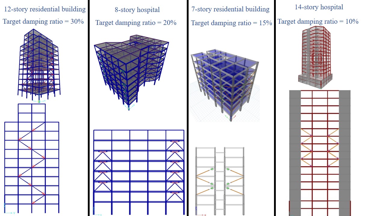
As shown in the figure, number of required viscous dampers and their characteristics depend on the dynamic properties of the structure, i.e. story mass, story stiffness, inherent damping ratio, and the target damping ratio which is intended to be achieved by the viscous dampers. Again, it should be emphasized that viscous dampers are not required in all stories.
Illustrated damper placements are obtained based on our exclusive algorithm. To use this algorithm for your own design, contact us.

DIAGONAL DAMPER PLACEMENT
One of the most common configuration for viscous dampers is the diagonal placement. The main advantage of this configuration is its simple installation and aesthetically pleasing features. However, in this configuration damper displacement would be smaller than the inter-story drift, i.e. relative story displacement, depending on the inclination angel. It should be pointed out that in this configuration, one of the damper ends is rigidly fixed to the extender, i.e. the brace, and the other end should be connected to the gusset plate with a true pinned connection. The term “true pinned” indicate that at the clevis of the viscous damper, spherical bearing should be used to provide true rotational freedom along all 3 axes. Spherical bearings are necessary to prevent any unintended flexural demands on the piston rod of the damper. To see spherical bearings in action, see this test video.
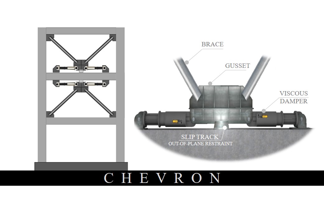
CHEVRON DAMPER PLACEMENT
Another widely used configuration for viscous dampers is the chevron configuration in which commonly two dampers simultaneously would be placed at a single bay. This configuration is appealing from architectural points of view. It is also appealing from structural view as damper displacement would be rather equal to the story drift (neglecting the limited brace deformations). However, damper installation in chevron configuration needs at least two extenders, i.e. braces, and three connection points and a slip-track connection at the apex of the two chevron brace. This slip-track connection is required to restrain out-of-plane displacements. Note that in chevron configuration, commonly both ends of the viscous damper should have true pinned connections, i.e. viscous dampers should have clevis with spherical bearings at both ends.

PANEL-TYPE DAMPER PLACEMENT
Similar to chevron configuration, in the panel-type configuration damper displacements can be close to the story drift (neglecting rotations of the upper and lower beams of the damped bay). Moreover, this configuration has minimal effects on architecture of the building as the dampers can be aligned with other structural and non-structural walls and partitions. In this configuration, both ends of the viscous damper should have true pins, i.e. clevis with spherical bearings. To achieve the best performance in this configuration, upper and lower beams of the damped bay should be rather rigid with minimal possible rotations.
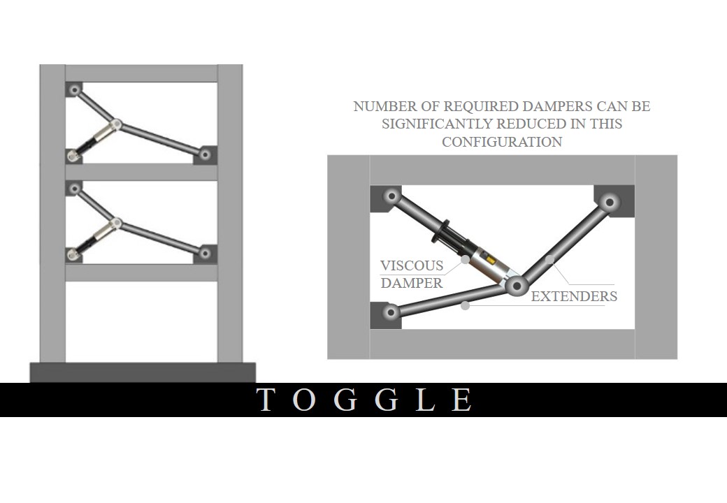
TOGGLE DAMPER PLACEMENT
One of the most appealing advantage of toggle placement is its amplification mechanism. That is, depending on the inclination angles of the braces, in this configuration damper displacement would be higher than story drift. This would increase viscous dissipated energy and amplify contribution of each viscous damper. In other words, using toggle configuration, number of required dampers can be significantly reduced to reach to a target damping ratio. Toggle configuration also amplifies damper force which means dampers with lower capacities (lower prices) can be used.
Note that, amplification factor in toggle configuration is highly sensitive to the inclination angles of the brace, so a damper placement in toggle configuration calls for tight tolerances. Moreover, in addition to the viscous dampers, true in-plane pinned connections should also be provided for the braces. To make a long story short, installation in toggle configuration would be more expensive than previous configurations. However, its main advantage is significant reduction in the required dampers. For further details about toggle configuration review this paper or watch this simulation movie.
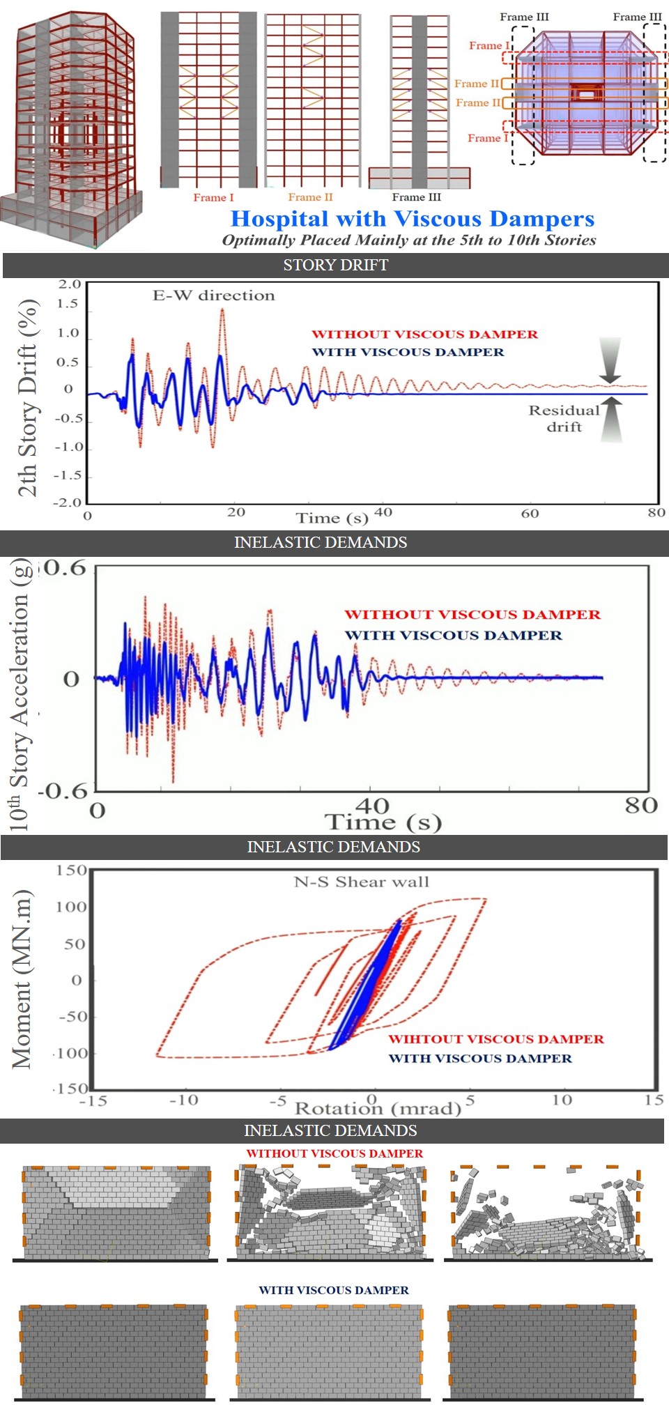
BENEFITS OF VISCOUS DAMPERS
Fluid viscous dampers have zero static stiffness and inject pure viscosity into the structure. This means modal vibration periods before and after installation of viscous dampers are virtually the same. As a result, fluid viscous dampers would almost always reduce ALL responses including story drifts, story displacements, story accelerations, story shear, inelastic demands, etc. illustrated figure is obtained results from a 14-story composite hospital with steel moment resisting frames and RC shear walls. The hospital is retrofitted with viscous dampers to reach to a target damping ratio of 15%. Not that the dampers are placed mainly in the 5th to 10th floors. This optimal placement is selected based on IRANDAMP’s exclusive placement algorithm.
To watch the simulated results of the illustrated 14-story hospital click here. To watch other simulations about contribution of viscous dampers visit the GALLERY.
Story Drift
Depending on the achieved target damping ratio, story drifts can be tuned based on the maximum drift of the original structure, i.e. without viscous damper, and the maximum allowable story drift which can be specified by the seismic code, or obtained based on the intended performance level. For example, if the maximum story drift of the original structure estimated to be 2.3% and you want to reduce it to 1.5%, you need to select a target damping ratio that reduce seismic responses by a reduction factor of 1.5. This reduction factor corresponds to a damping ratio of about 20%. So you need to select damper characteristics and placement to reach to 20% damping ratio.
Story Acceleration
Viscous dampers not only reduce story drifts and displacements, but also result in a significant reduction in story accelerations (both peak story acceleration and story acceleration spectrum). By reducing story accelerations, inertial forces and story shears would be reduced which means less demands on the main structural elements, including beams, columns, foundations and the soil beneath the foundation. The amount of reduction in story acceleration can be estimated by the reduction factor-damping ratio curves. For example if you want to reduce story accelerations by a factor of 2, you need to increase damping ratio to a value of about 30%. Note that viscous dampers guarantee story acceleration reduction as they add no lateral stiffness to the building and inject pure viscosity. Also note that the reduction factor-damping ratio curves are only applicable for buildings with viscous dampers, oil dampers, or tuned mass dampers which add no stiffness to the building.
Inelastic Demands
Viscous dampers reduce story drifts so it is not surprising to point out that they also reduce inelastic demands on structural elements. Plastic rotations of beams, columns and shear walls would be reduced thanks to the added viscosity. This is extremely crucial from resiliency point of view. Note that less inelastic demands also mean less residual deformations.
Non-Structural Elements
As mentioned before, viscous dampers reduce story accelerations. Therefore, it is obvious that viscous dampers also reduce seismic demands on non-structural elements and equipment inside the building.
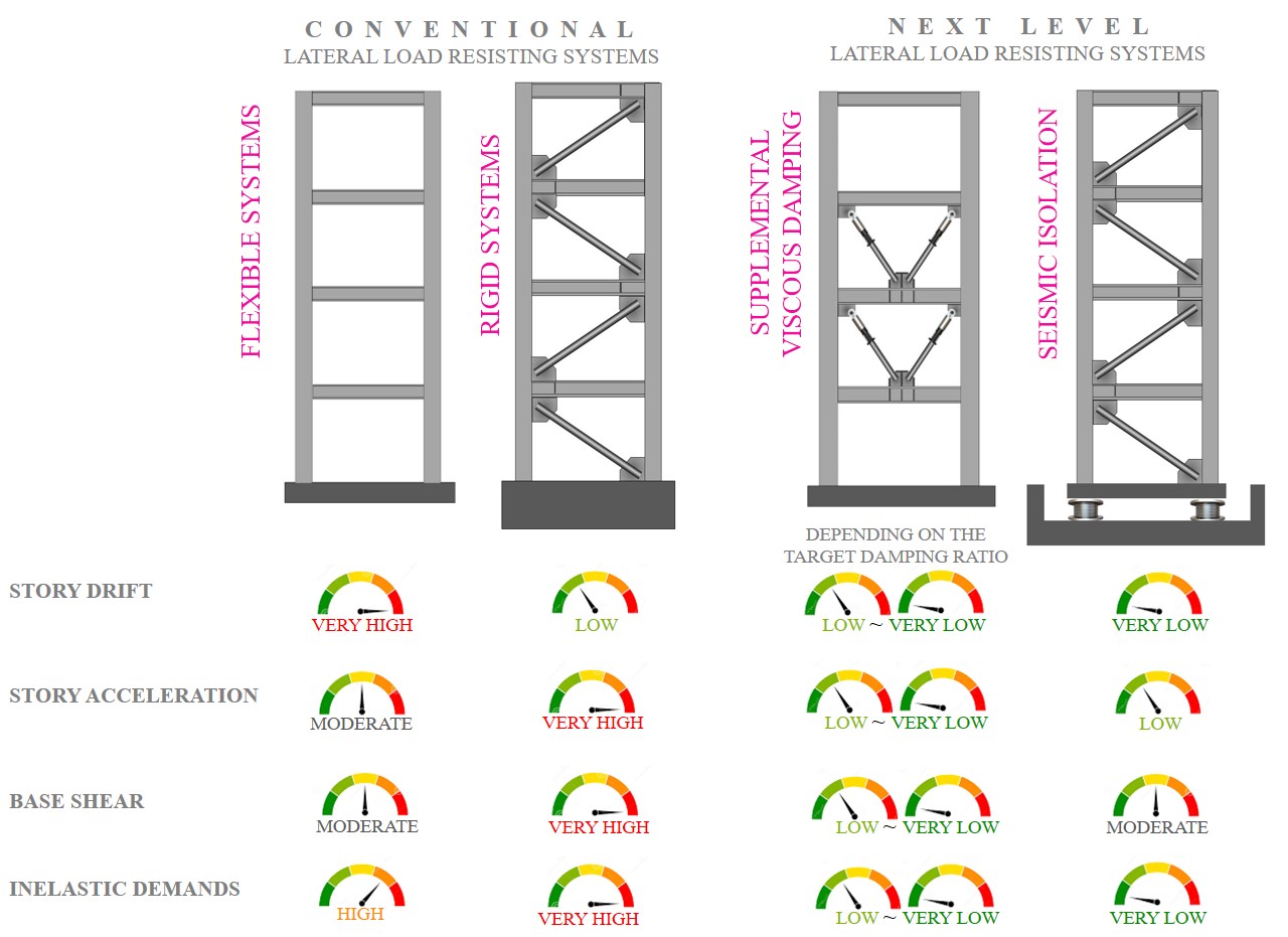
WHAT IS THE PROBLEM WITH CONVENTIONAL SYSTEMS?!
Why conventional lateral load resisting systems should be equipped with supplemental viscous damping or seismic isolation? To answer this question, four main seismic criteria are listed in the figure to compare conventional and modern systems.One of the main problems of conventional systems is that they excessively rely on inelastic behavior of structural elements to dissipate input energy. In this way, the main structural elements would be damaged and may require significant rehabilitation and upgrading after the earthquake. Moreover, in conventional systems, to reduce inter-story drifts, the only option is to increase lateral stiffness which would amplify story accelerations, inertial forces and base shear. So in conventional systems, it is not possible to simultaneously reduce both story drifts and accelerations. Modern systems, i.e. lateral load resisting systems with supplemental viscous dampers or with seismic isolations, have solved the problem and all dynamic responses can SIMULTANIOUSLY, be reduced.
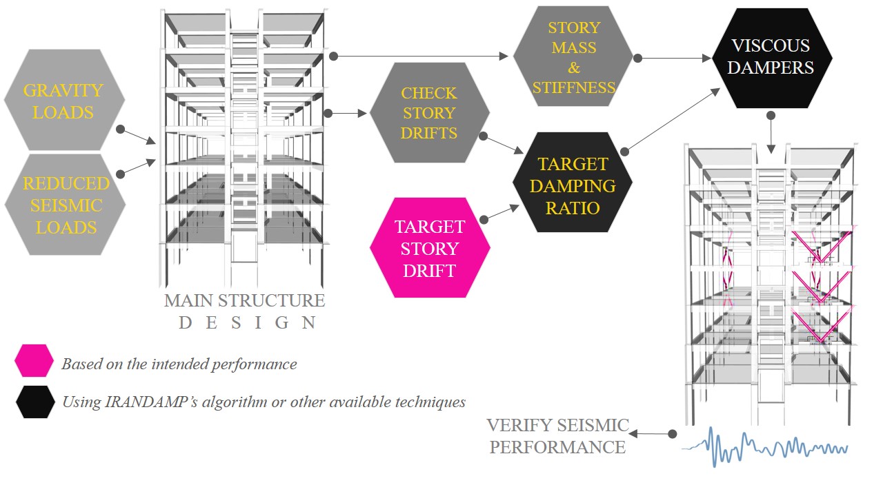
MAIN STEPS TO DESIGN VISCOUSLY DAMPED BUILDINGS
Believe it or not, seismic design procedure of buildings with viscous dampers is quite straightforward. The procedure can be summarized into three main steps,
Step 1. Design the main structure without viscous dampers. In this step, all gravity loads and reduced seismic loads should be considered. You do not need to be worry about story drifts in this step. Reduced seismic load corresponds to 75% of the seismic loads in most cases. This reduction, however, is not as important as it appears because the dominant design parameter is story drift rather than strength. So sometimes you may want to consider unreduced seismic loads in this step. Again note that story drifts can surpass the allowable values in this step.
Step2. Based on the maximum story drift of the main structure (without damper) and the target story drift, you need to select a target damping ratio. For example if the maximum story drift of the undamped structure is 2% and your target story drift (say based on IO plastic hinge rotations) is 1.2%, then you need to achieve a damping ratio of about 25%. Probably you have noticed that you should avoid very weak main structures with very high undamped story drifts. Having the target damping ratio and story mass and story stiffness of the main structure, viscous dampers can be optimally designed and placed by IRANDAMP’s algorithm. Other algorithms are also available or the designer may adopt a trial and error procedure to select characteristics and placements of the viscous dampers. However, the latter trial and error technique is not justified anymore.
Step3. After placing viscous dampers, seismic performance of the building should be verified. In most cases, this would be carried out using nonlinear time history analyses.
To watch a comprehensive tutorial about practical steps for seismic design of buildings with supplemental viscous dampers, CLICK HERE.
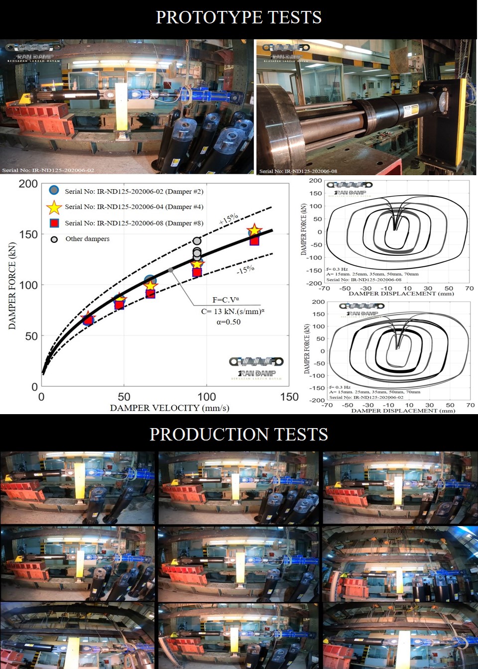
PROTOTYPE AND PRODUCTION TESTS
Viscous dampers are regarded as high-tech and rather expensive anti-seismic devices and the designers and owners of the structure must ensure the correct performance of the purchased viscous dampers. Two types of tests are commonly carried out on viscous dampers before their installation, prototype tests and production tests. Prototype and production tests report of IRANDAMP’s viscous dampers installed in Nobonyad Tower in Tehran can be found here (the report is in Persian). Note that these velocity-dependent dampers are not disposable devices and neither prototype nor production tests would damage them. So after the tests, all of the tested dampers would be ready to be installed in the structure and you do not need to order additional damping devices.
Prototype Tests
The main intention of prototype testing is to evaluate performance of the damper in terms of force-velocity behaviors and stability of cyclic loops. Loading protocols and acceptance requirements of viscous dampers during prototype tests are commonly stipulated by the applicable code of practice, for example chapter 18 of ASCE 7. However, the most important acceptance criteria are compliance of the force-velocity curve with the predetermined damping coefficient and velocity exponent as well as stability of the cyclic loops with the same amplitudes and frequencies. No yielding, fracture, rupture, leakage or any kind of deterioration should be seen during the tests, or else the damper would be rejected. During prototype tests, viscous dampers would be subjected to different dynamic loading protocols. Click here to watch prototype tests carried out on IRANDAMP’s viscous dampers or visit the GALLERY.
Production Tests
Production tests are required to verify expected performance of the manufactured viscous dampers. Production tests are not as comprehensive as prototype tests and in most cases only a single loading protocol with a limited number of cycles, say 5 cycles, and fixed amplitude and frequency would be considered during production tests. Loading protocols and acceptance requirements of viscous dampers during production tests are commonly stipulated by the applicable code of practice, for example chapter 18 of ASCE 7. Click here to watch production tests carried out on IRANDAMP’s viscous dampers or visit the GALLERY. Again it should be emphasized that, viscous dampers are not disposable and prototype or production tests would not damage them.
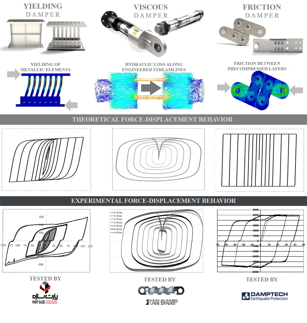
DIFFERENT SEISMIC DAMPERS
The purpose of this text is to review the main advantages and limitations of the most widely used seismic dampers. It is not intended to direct you to a specific damper type. Nowadays all commercial dampers have stable cyclic behaviors with significant energy dissipation capabilities, much better than that of conventional lateral load resisting systems.
Displacement-Dependent Dampers
Yielding and friction dampers are the most widely used displacement-dependent dampers which work based on yielding of metallic components and friction between pre-compressed layers, respectively. These dampers have quite good energy dissipation capability with stable cyclic behaviors. However their damping effect would only be activated during oscillations which are large enough to make yielding or slippage in the damper. Therefore, in the case of in yielding and friction dampers, no energy dissipation is expected to occur during service-level earthquakes or small oscillations of a design-level earthquake. In addition, displacement-dependent dampers would increase lateral stiffness of the structure which is beneficial from story drift point of view, but care should be exercised if reduction in story accelerations and inertial demands are among intents of the design. Residual deformation is another consideration of displacement-dependent devices. In general, the main lateral load resisting system should have enough elastic stiffness to be able to re-center the yielded/slipped devices.
Velocity-Dependent Dampers
Fluid viscous dampers are the most widely used velocity-dependent dampers which work based on hydraulic energy loss inside the damper. They have stable cyclic behaviors even during high duration wind and wave excitations with thousands of cycles. Moreover, these velocity-dependent dampers are not disposable and do not need to be replaced even after a design-level earthquake. Another advantage of viscous dampers is the fact that they are velocity-dependent which means they work even during tiny oscillations. So full time damping enhancements are expected during service-level and design-level earthquakes. Very large damping ratios in the range of 30% to 40% can also be achieved by viscous dampers as they have zero static stiffness and inject pure viscous damping into the structure. However, these high-tech devices are rather expensive. Therefore, a balance need to be achieved between initial construction costs and the superior advantages of viscous dampers. It is not unlikely to combine viscous dampers with other yielding or friction dampers to reduce initial construction costs, especially in the case of high-rise buildings.
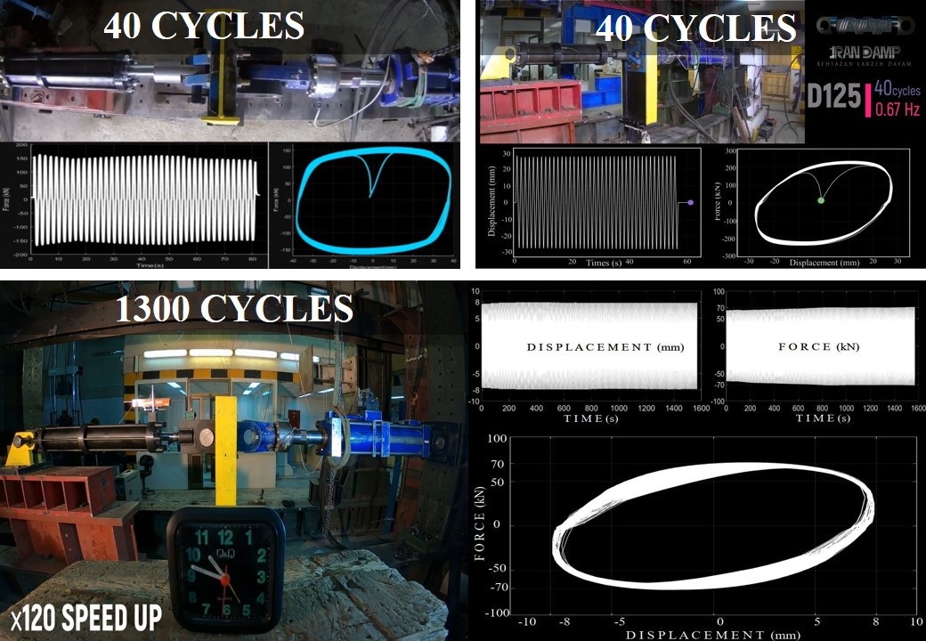
HIGH DURATION LOADS
Wind and wave loads are considered as high duration dynamic loads with thousands of continuous cycles. Viscous dampers are not sensitive to fatigue and have stable cyclic behaviors even under thousands of cycles. IRANDAMP has carried out some high duration tests on its manufactured products. As shown in the figure, viscous dampers revealed no deterioration during high duration loads. During a seismic excitation, damper temperature would raise by less than 5 Celsius degrees. However, in the case of high duration excitations, damper temperature could raise by more than 100 Celsius degrees. Nowadays, most commercial viscous dampers have temperature compensator mechanisms by which damper force would be rather insensitive to the temperature. Fortunately most high duration excitations, e.g wind and wave loads, have small excitation frequency which gives enough time to transfer the generated heat into the surrounding.
As a result, viscous dampers are well suited vibration control devices for suppressing wind-induced vibrations on tall buildings and wave-induced vibrations on offshore structures. Carried out studies indicated that viscous dampers can significantly increase fatigue life of offshore structures. Click here to review a research paper and here to watch the associated video about this topic.

DAMPER CONNECTION TO RC JOINTS
Dampers can be connected to RC joints using a different details. Four details are discussed here and the visitors can review this text book for further details about damper-to-RC joint connections.
Type I
This connection is well suited for new constructions in which the anchor plate and its headed studs (or J Bolts) are placed before concrete casting. Supplemental reinforcements are placed at the location of headed studs to prevent excessive cracking at the regions close to the headed studs. Note that, beam’s plastic hinge would be relocated toward the midspan which should be considered during performance-based seismic design procedure.
Type II
This connection can be used for both new constructions and rehabilitation projects. In this detail no plastic hinge relocation is expected and plastic rotation capacity of the beam would be enhanced due to the provided confinement from the post-tensioned anchor plates.
Type III
This unconstrained connection has minimal interaction with frame and can be used not only in seismic upgrading projects, but also in new constructions. Additional confinement would be provided for the beam and the beam’s plastic hinge is expected to occur close to the column face. Note that this connection would result in additional shear demands on the beam. However, in the case of viscous dampers, this demand would be out-of-phase with other forces.
Type IV
This connection is another unconstrained connection detail which similar to the connections type II and III can be used for both upgrading and new construction projects. No plastic hinge relocation is expected in this connection and an additional but out-of-phase demands would be imposed on the column which should be considered. This detail is not recommended for displacement-dependent energy dissipating devices such as Buckling Restrained Braces (BRBs) and other yielding or friction devices.
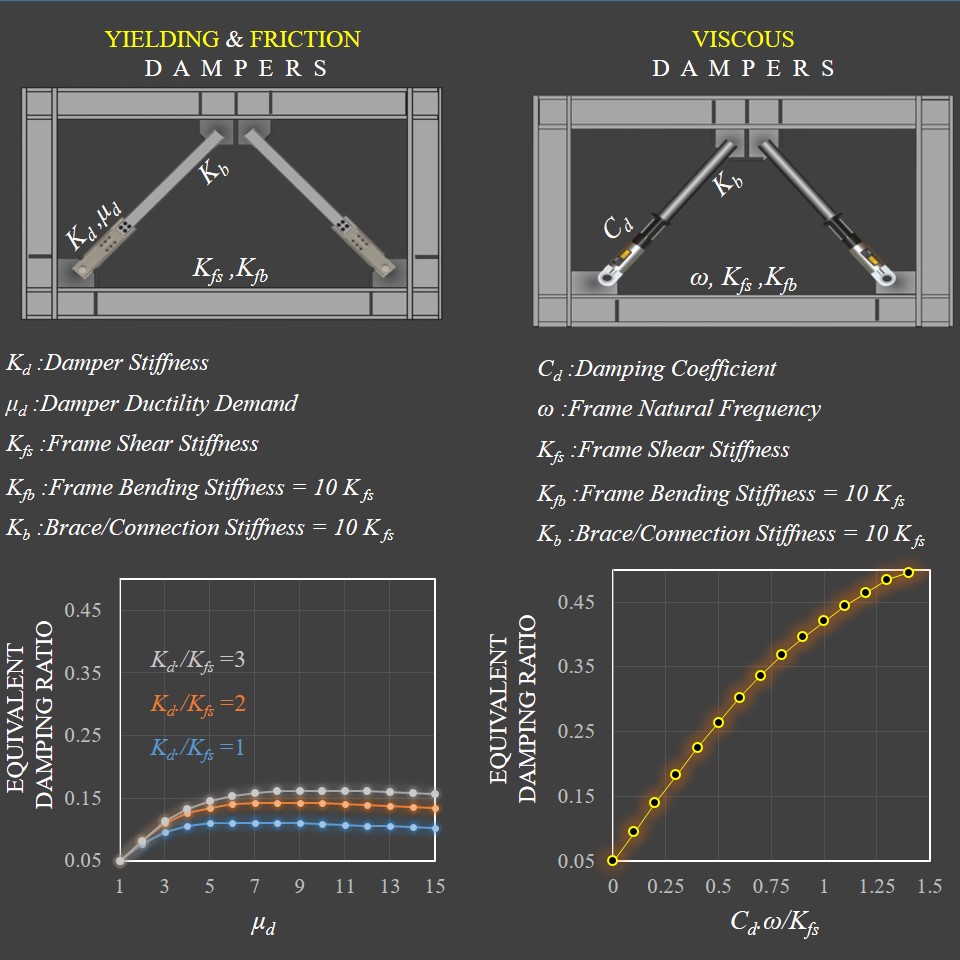
MAXIMUM ACHIEVABLE DAMPING
One of the most fundamental questions is “How much the damping ratio of the structure can be increased using seismic dampers?” Most seismic codes and guidelines remained silent, when it comes to this question. Maximum achievable damping ratio highly depends on the damper type, damper properties, and dynamic characteristics of the main structure. For example, as shown in the figure, in the case of yielding or friction dampers, maximum achievable damping ratio is about 16% considering all practical considerations. Presented graph can be used to select the optimum damper ductility demand, as well. Note that ductility demand is defined as the ratio of maximum damper deformation to its yield deformation. In the case of friction damper, yielding deformation corresponds to the damper deformation just before damper activation, i.e. damper sliding.
On the other hand, technically there is no limitation on the maximum achievable damping ratio in the case of viscous dampers. However, considering practical and economical limitations damping ratios higher than 40% are not common in civil engineering structures. So most structures with viscous dampers are designed for a target damping ratio of less than 40%. Note that, super high damping ratios are easier to achieve in the case of more flexible structures such as seismically isolated buildings and bridges. Presented graphs are obtained based on the closed-form formulations developed by Kasai et al.
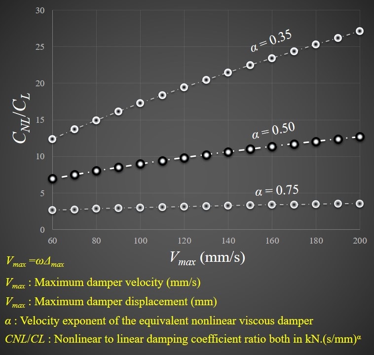
LINEAR-NONLINEAR CONVERTOR
Most closed-form formulations in classic text books, design procedures and algorithms have been developed based on linear viscous dampers, i.e. viscous dampers with linear force-velocity behavior. Most engineers prefer to use nonlinear viscous dampers to reduce maximum damper forces without losing energy dissipation. So nonlinear viscous dampers with velocity exponent in the range of 0.3 to 0.75 are quite common. Fortunately, for each linear viscous damper, an equivalent nonlinear viscous damper can also be defined. For example, presented curves are obtained based on the formulation proposed by Lin and Chopra which is based on equalizing dissipated energy during one harmonic cycle with frequency of ω and amplitude of Δmax. In practical applications, ω is fundamental frequency of the structure and Δmax is the estimated maximum deformation of the damper.
Obviously maximum velocity of the viscous damper should be estimated before converting to its equivalent nonlinear counterpart. This can be achieved using a spectrum analysis considering the enhanced damping ratio. IRANDAMP verifies accuracy of this simple technique.
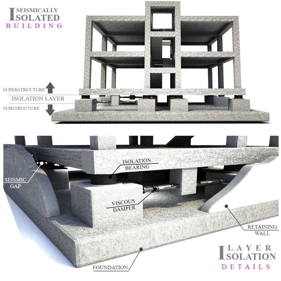
SUPPLEMENTAL VISCOUS DAMPERS IN SEISMIC ISOLATION SYSTEMS
Seismic isolation is one of the best vibration control strategies in which fundamental period of the structure would be lengthened using elastomeric or sliding bearings. Isolation systems with fundamental periods in the range of 4s to 6s would lead to significant reduction in seismic demands. However, significant shear deformations are expected to occur in the isolation bearings. Accordingly, viscous dampers have gained popularity in order to reduce deformation demands of the isolation bearings without affecting flexibility of the isolation system. Thanks to the viscous dampers, super flexible bearings can now be used in the isolation systems to reach to significant isolation properties.
A simplified design procedure for seismic isolation systems with supplemental viscous damping is proposed by JSSI. The procedure uses energy balance concept and can be used for initial design of isolation systems with different isolation bearings and supplemental viscous dampers.
To watch an animation about seismic isolation systems with supplemental viscous dampers click here.
To watch simulation results of a seismically isolated building with and without supplemental viscous dampers, click here.
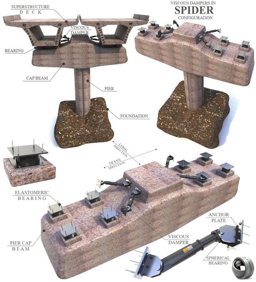
SUPPLEMENTAL VISCOUS DAMPERS IN BRIDGES
Applications of viscous dampers are not limited to buildings and this superior vibration control technology has been widely used in other infrastructures, as well. As shown in the figure, viscous dampers can be placed at the superstructure-to-substructure interface of bridges to improve damping ratio along both longitudinal and transverse directions. Because of the velocity-dependency, viscous damper provides no restraint against thermal deformations of the bridge. Using viscous dampers, force and deformation demands on the bridge piers, bearings and abutments would be significantly reduced. Moreover, viscous dampers reduce superstructure accelerations which means less seismic demands on the lighting, signal and sign structures.
In highly damped bridges, the main source of energy dissipation is the viscous dampers rather plastic hinges at the bridge piers/bents. This indicates that just like the superstructure, the substructure can also be designed to remain elastic during a design-level seismic event which is a dramatically beneficial design strategy. Note that bridges are among the most important infrastructures and need to remain mainly elastic and operational even during a design-level earthquake. Viscous dampers can be used to reach to this goal for new and existing bridges.
PLACEMENT IN AN ASYMMETRIC ARRANGEMENT
Unlike other force resisting systems and seismic dampers, viscous dampers are velocity-dependent devices with zero (or very small) static stiffness. This means that viscous dampers do not change center of stiffness of the building even if they were placed in an asymmetric arrangement. The simulation presented in this VIDEO shows story torsions of an RC moment frame building with and without viscous dampers. The viscous dampers have asymmetric arrangement along the X direction and Sarpol-e Zahab earthquake record is imposed along the X direction. As expected, even asymmetric viscous dampers reduce story torsion in all stories. Damper placements was selected based on IRANDAMP’s optimum placement algorithm to increase X-direction damping ratio from 5% to 15%.
Of course in the case of no architectural limitation, symmetric arrangements are commonly the preferred choice.